Multilayers Flex PCB 
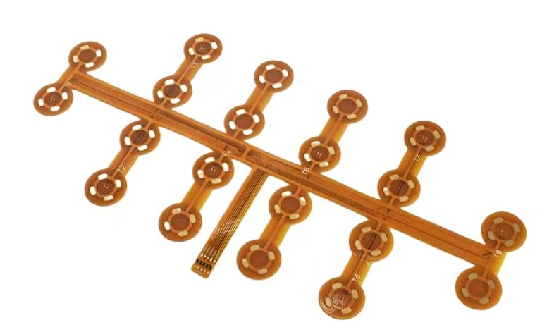
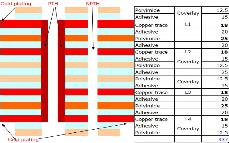
A multi - layer flex circuit pertains to a flexible circuit configuration featuring more than two circuit layers. Comprising three or more flexible conductive layers, each is discreetly separated by intervening flexible insulating layers. These conductive layers establish connectivity via metalized vias and meticulous plating processes, thereby creating seamless conductive pathways between different strata. The outermost layers are composed of polyimide insulating materials, which provide essential protection and insulation properties.
Typically, a multi - layer flexible circuit is ingeniously assembled by integrating several double - sided flex circuits and single - layer flex circuits. As a result, there isn't a pre - fabricated flexible copper - clad laminate readily available for such constructions. Throughout the entire production cycle, the lamination of these multiple layers can be either continuous or non - continuous. When the design demands prioritize maximum flexibility, continuous lamination might not be the optimal approach. This is because continuous lamination could potentially restrict the inherent flexibility of the individual layers, thus compromising the overall flexibility of the final product.
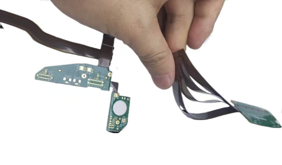
Constructed from polyimide, the multi - layer flexible circuit offers a significant weight advantage, being at least one - third lighter than a rigid FR4 PCB. Nevertheless, the presence of multiple layers inevitably leads to a reduction in flexibility compared to single - sided and double - sided flexible PCBs. Fortunately, in most practical applications, these products do not necessitate an extremely high degree of flexibility. In the current market landscape, 4 - layer, 6 - layer, and 8 - layer circuits are the most sought - after and widely utilized configurations. In contrast, 10 - layer circuits or those with an even higher layer count are rarely employed due to their increased complexity, cost, and potential performance trade - offs.
Key Capabilities:
- Multilayer circuitry-from 3 to 14+ layers
- Min LW/LS: 4mil/4mil
- Adhesive-based and adhesiveless constructions, including thermoplastic and thermoset stiffener attachment.
- Polyimide substrates: 1/2mil – 4mil
- Copper: 1/3OZ – 2OZ, RA or ED type
- Stiffeners include Polyimide (0.075-0.20mm), FR4 (0.15-2.0mm), and punched or formed metal parts (0.075-1.0mm)
- Low-cost, conventional fabrication and lamination completed with PTH based plating
- Screened inks, photo-imageable soldermasks, or laminated coverlay dielectrics
- Surface finishes: ENIG, electroplated nickel/gold, immersion silver, tin,
- EMI Shielding
As a professional manufacturer of a multi-flex circuit boards in China, I-tech electronics co.,ltd can always make your circuit board dreams come true. Welcome to contact us anytime for inquiries about multi-layer flexible circuits.


