
Rigid-flex Circuits(Rigid-Flex PCB)
 Rigid Flexible Circuit (Rigid-flex circuit board, Rigid-flex pcb) is a circuit board composed of Rigid circuit board and Flexible circuit board. It is selectively interconnected by an epoxy pre-preg bonding film and electronically connected via plated through holes (PTH) and vias, almost resembling a multi-layer flex circuit.
Areas requiring extra support are designed as rigid, while corners and areas demanding additional space and flexibility are designed as flexible. Therefore, it can enjoy the advantages of both rigid boards, such as rigidity and flatness, and flexible circuits, such as flexibility and bendability. Rigid-flex circuits provide higher component density and better quality control.
Typically, the rigid parts made of FR4 PCB can have one layer to multiple layers, and on the outer layers, most of the FR4 PCB will have one layer to multiple layers in most instances. The vital part is the flexible circuit that connects the Rigid PCB, which can also be one layer or multiple layers. Currently, we are capable of manufacturing rigid-flex circuits with over 50 layers.


Advantages of Rigid Flex Circuit
High-Density Applications: The rigid area of a rigid flex circuit is employed for high-density device placement. Additionally, finer line widths and spacings are permitted in flexible circuits, enabling higher density. Denser device layouts and lighter conductors can be incorporated into a product, creating space for additional product features.
Broader Applications: Advances in rigid circuit board technology have expanded the applications of electronic products, ranging from communication, computer, and consumer electronics to medical, automotive, and military electronics.
The increasing demand for more powerful and smaller products drives the need for multiple layers to accommodate denser, finer line widths and spacings, and smaller hole sizes.
Highly Complex Configurations
Fewer Electronic Components Required
Reduced Interconnections
Reduced Package Size and Weight
Furthermore, the air gap widely utilized in multi-layer flex circuits can also be employed, and other features such as controlled impedance (insert impedance-control.htm), EMI shielding, panelization, stiffeners, PSA, and Circuit Assembly (SMT) are also available.
Rigid Flexible Circuit Capability
As a professional manufacturer of rigid flexible circuit board in China, We always try to improve our capability to produce more rigid-flex circuit board to our customers. Here is major capability:
1-10 flexible layers; multiple flex layers in either bonded or air gap configuration
1-32 Rigid layers
Flex Core Materials: Polyimide (PI): 1/2 mil to 4 mils in either adhesive or adhesives constructions
Copper thickness: 1/3 OZ – 2 OZ RA or ED type (insert material/copper-foil.htm) in flexible circuit; 1/2OZ to 10 OZ in rigid circuits;
Coverlays: 1/2 mil to 2 mils polyimide
Stiffeners material: polyimide, FR4, stainless steel, aluminum,copper
Rigid Materials: 130, 170, 180 TG FR4, low flow prepreg
EMI/RF shielding films
Blind and buried vias available
Any layer available
Controlled impedance: 50 ohm, 90 Ohm, 100 Ohm, 110 Ohm and other value
Surface finishing: ENIG, ENEPIG, gold plating, gold fingers (3-30u” Au), Immersion silver
IPC 6013 – Class II & Class III available
Customer Quality Standard is Top Priority, We Fully understand for The Special Characteristic and Requirement from Customer,Which is Identified by Our engineering Team and QA Customer Standard Team.
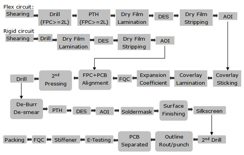
Rigid Flex Circuit Manufacturing Process:
Manufacturing of rigid-flex PCB is much more complicated than other types of flexible circuit, here are simple manufacturing steps for your reference:
We offer a wide range of sizes of rigid flexible circuit boards with different layers. All Rigid-Flex Circuits are subjected to electronic testing that reflects all Gerber data to ensure continuity and meet other data requirements.
We can provide fast prototypes within 3 to 7 days, ensure on-time delivery, and guarantee excellent quality for you. Please contact us today for more information about rigid flexible circuits.